Story Time
I’ll give a bit of a backstory before I get explaining. A few months ago, my senior bought a mechanical keyboard from Amazon, specifically the Cosmic Byte Artemis 68. It was a pretty standard keyboard with brown switches and RGB lighting. Well, unfortunately, while performing a firmware update, his loose wire got disconnected and ended up with a bricked keyboard. He tried to fix it for a while but could not do much and gave up.
Now, I got my hands on a spare bricked keyboard which was as good as paperweight.
I knew that Raspberry Pi Pico could be used as an HID device (I made a simple rubber ducky once :P) so I went ahead and started searching if something like a keyboard had been made. Of course some amazing people out there have done the same already, better yet they’ve made a full keyboards completely from scratch.
Tinkering with the Keyboard
I opened up the keyboard and took out the PCB to see the layout. I could clearly see the matrix of switches and could identify the rows and columns. Using a multimeter I checked the continuity between the switches and the pins on the PCB. After a while, I was able to map out the rows and columns of the keyboard matrix.
Mapping out the rows and columns was a bit tedious but I trusted my senior Abhijit CB to do the soldering and mess with the board.
The Process
With the tinkering done, I moved on to making it a keyboard. I had to use the CircuitPython HID library to make the Pico act as a keyboard. The library is pretty straightforward and easy to use.
Turning the Pico into an HID
First, I had to install CircuitPython on the Pico to get the HID capabilities. Following the official guide to do is easy and very easy to get started with Circuit Python. Once you have CircuitPython installed, you can copy the adafruit_hid library to the lib folder on the Pico.
This sets out base for the project. I used Thonny IDE to write the code and upload it to the Pico.
Act as a Keyboard
To make the Pico identify as a keyboard, I need to assign the keyboard device identifier from the usb_hid.devices list.
import usb_hid
keeb = Nonefor dev in list(usb_hid.devices):    if ( (dev.usage == 0x06) and        (dev.usage_page == 0x01) and        hasattr(dev, "send_report") ):        keeb = devif keeb == None:    raise Exception("Device cannot be found")
The Keyboard Matrix
The keyboard I am working on doesn’t follow the conventional layout. So, I had to create the matrix according the layout I mapped out earlier.
matrix = [ [ Keycode.ESCAPE, Keycode.ONE, Keycode.TWO, Keycode.THREE, Keycode.FOUR, Keycode.FIVE, Keycode.SIX, Keycode.SEVEN, Keycode.EIGHT, Keycode.NINE, Keycode.ZERO, Keycode.MINUS, Keycode.EQUALS, Keycode.BACKSPACE ],19 collapsed lines
[ Keycode.TAB, Keycode.Q, Keycode.W, Keycode.E, Keycode.R, Keycode.T, Keycode.Y, Keycode.U, Keycode.I, Keycode.O, Keycode.P, Keycode.LEFT_BRACKET, Keycode.RIGHT_BRACKET, Keycode.BACKSLASH ], [ Keycode.CAPS_LOCK, Keycode.A, Keycode.S, Keycode.D, Keycode.F, Keycode.G, Keycode.H, Keycode.J, Keycode.K, Keycode.L, Keycode.SEMICOLON, Keycode.QUOTE, Keycode.RETURN, Keycode.ENTER ], [ Keycode.LEFT_SHIFT, Keycode.Z, Keycode.X, Keycode.C, Keycode.V, Keycode.B, Keycode.N, Keycode.M, Keycode.COMMA, Keycode.PERIOD, Keycode.FORWARD_SLASH, Keycode.RIGHT_SHIFT, Keycode.PAGE_UP,Keycode.GRAVE_ACCENT ], [ Keycode.LEFT_CONTROL, Keycode.LEFT_GUI, Keycode.LEFT_ALT, Keycode.SPACE,Keycode.SPACEBAR, Keycode.RIGHT_ALT, Keycode.RIGHT_GUI, Keycode.RIGHT_CONTROL, Keycode.LEFT_ARROW, Keycode.UP_ARROW, Keycode.DOWN_ARROW, Keycode.RIGHT_ARROW, Keycode.PAGE_DOWN, Keycode.DELETE ],] # matrix[row][col]Setting up the GPIO Pins
Now that the matrix is set up, I need to set the input rows and output columns. I used the digitalio library to set the pins as input or output.
input_pins = (board.GP6, board.GP7, board.GP8, board.GP9,board.GP10) # 5 input rows
input_pin_array = [] # DigitalIO array for inputs.
output_pins = (    board.GP11, board.GP12, board.GP13, board.GP14, board.GP15,    board.GP16, board.GP17, board.GP18, board.GP19, board.GP20,    board.GP21, board.GP22, board.GP26, board.GP27) # 14 output columns
output_pin_array = [] # DigitalIO array for outputs.
# Initialise DigitalIO pins.for pin in input_pins:    key_pin = digitalio.DigitalInOut(pin)    key_pin.direction = digitalio.Direction.INPUT    key_pin.pull = digitalio.Pull.DOWN    input_pin_array.append(key_pin)
for pin in output_pins:    key_pin = digitalio.DigitalInOut(pin)    key_pin.direction = digitalio.Direction.OUTPUT    key_pin.drive_mode = digitalio.DriveMode.PUSH_PULL    output_pin_array.append(key_pin)
What this code does is it sets up the GPIO pins on the Pico as input or output. The input pins are connected to the rows of the keyboard matrix and the output pins are connected to the columns of the keyboard matrix. This matrix was created so that I don’t have to map each key to a separate GPIO pin. This way I can use a 5x14 matrix to map out the 68 keys using only 19 GPIO pins.
Keyboard Scanning
Now that the matrix and the pins were set up, the keypresses can now be scanned and sent to the computer. That is exactly what the following code does. It scans the matrix and sends the keypresses to the computer.
keys_pressed = []report_array = [0x00] * 8
while True:    for col in range(len(output_pin_array)):        output_pin_array[col].value = True        for row in range(len(input_pin_array)):            if (matrix[row][col] >= 0xE0) and (input_pin_array[row].value):                report_array[0] |= Keycode.modifier_bit(matrix[row][col])            elif input_pin_array[row].value:                keys_pressed.append(matrix[row][col])        output_pin_array[col].value = False    if len(keys_pressed) > 6:        for i in range(2,8):            report_array[i] = 0x01    else:        for i in range(6):            report_array[i+2] = keys_pressed[i] if i < len(keys_pressed) else 0    keeb.send_report(struct.pack("8B", *report_array))    report_array = [0x00] * 8    keys_pressed = []
Code explanation
The keys_pressed list is used to hold the normal keycodes that are pressed. The report_array is used to hold the final report that will be sent to the computer.
for col in range(len(output_pin_array)): output_pin_array[col].value = TrueThis loop iterated through each column of the matrix and sets the corresponding output pin to HIGH. This is done to scan the column for any keypresses. It lets me check the active rows for that column.
for row in range(len(input_pin_array)): if (matrix[row][col] >= 0xE0) and (input_pin_array[row].value): report_array[0] |= Keycode.modifier_bit(matrix[row][col]) elif input_pin_array[row].value: keys_pressed.append(matrix[row][col])This loop iterates through each row of the matrix and checks if the corresponding input pin is HIGH. If it is, it means that the key at that row and column is pressed. If the key is a modifier key (like Shift, Ctrl, Super), it adds the modifier bit to the first byte of the report_array. If it’s a normal key, it adds the keycode to the keys_pressed list.
output_pin_array[col].value = FalseThis line sets the output pin back to LOW after scanning the column.
if len(keys_pressed) > 6: for i in range(2,8): report_array[i] = 0x01A standard keyboard can only hold 6 keys at a time. If more than 6 keys are pressed, it adds the Rollover Error keycode (0x01) to the report_array.
else: for i in range(6): report_array[i+2] = keys_pressed[i] if i < len(keys_pressed) else 0Slots the keycodes from the keys_pressed list into the report_array. If there are less than 6 keys pressed, it fills the remaining slots with 0.
keeb.send_report(struct.pack("8B", *report_array))report_array = [0x00] * 8keys_pressed = []Finally, it sends the report_array to the computer using the send_report method.
After sending the report, it resets the report_array and keys_pressed list for the next scan.
Should only act as a Keyboard
To ensure that the Pico only acts as a keyboard and not as the usual storage device, I added the following code on the Pico.
import storagestorage.disable_usb_drive()The Final Product
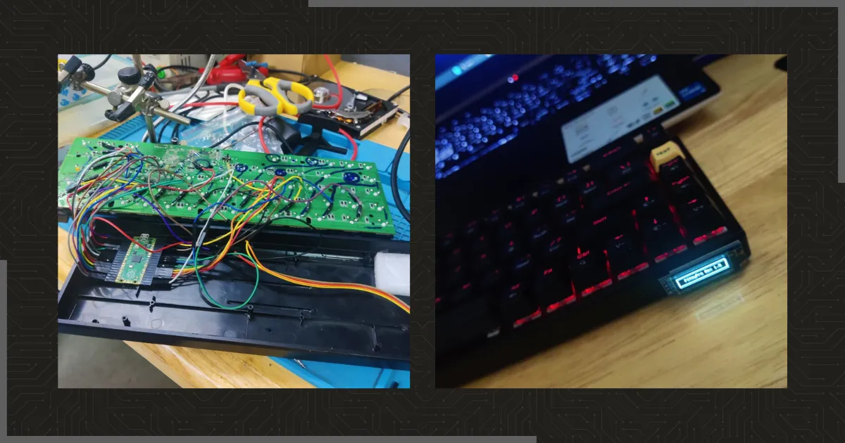
And that’s it! I had a fully functional keyboard (except the media keys and the other stuff). The only thing left to do is to pack everything back together in the plastic case and it’s done ✅. (I also added some flair to it! ✨)